The first in th world (any-fuel) home power station VTES:
- provides private houses with "green" electricity and heating
- runs on any biofuel (including solid ones: wood, pellets etc.)
- is powered by the innovative steam engine

contacts:
VKontakte
The first model of KROPAT project: VTES-1
The first power station developed within the framework of the KROPAT project is any-fuel home-class powerblock (model VTES-1). According to the conventional terminology, VTES-1 is a cogeneration unit (or CHP - combined heat and power), because it generates both electricity and useful heat energy. This heat is used by the consumer for heating of house and hot water supply.
VTES-1 "KROPAT" is designed to provide private houses with electric and thermal energy and to cover all needs in electricity and heating of standard household. VTES can run on any combustible fuel including solid biofuels, such as pellets, firewood, agricultural and wood-processing wastes, etc.
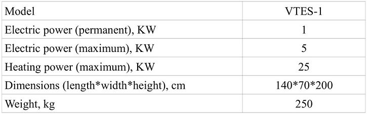
The main technical characteristics of VTES-1 are shown in the table below. These parameters are approximate and based on the data of the VTES-1 prototype.

The prototype of VTES-1
VTES is consisted of several functional units, which work in the closed energy system. All that system operates as follows. Water being forced by the feed pump is supplied from the water tank to the steam boiler. When fuel combusts in a burner in the steam boiler, water is heated, evaporated and comes to working pressure in the form of water steam. Then steam is directed to the steam engine, which, under the action of steam, makes useful work by driving the electric generator (alternator). The alternator generates an electric current that is being used by the consumer. After engine the exhaust steam passes to the condensation heat exchanger of "steam-water" type. That exhanger is cooled by passing coolant (water or antifreezer) which circulates in home heating system. In the exchanger steam gives its heat to coolant and condenses into water. The heated coolant passes its thermal energy to the consumer for heating and hot water supply. Condensed water is drained from exchanger to the water tank. From tank the water is pumped to the boiler again, and it closes the working cycle of the VTES.

The overall scheme of VTES-1 is depicted in the picture placed above. The scheme shows the main elements of VTES and the flows of energy, steam and water between them. All elements of VTES are enclosed in a monoblock case, except for heating radiators. The heating radiators shown in the diagram are not included in VTES-1, and can be replaced with another heating appliances. For example, it can be an air heating device equipped with a fan and a air/water heat exchanger.
The dimensions of the VTES-1 casing correspond to the sizes of a large household refrigerator. The VTES is located on the floor, in a separate space in the house intended for the boiler room.
VTES is powered by steam engine of original innovative "KROPAT" design. The engine is an uniflow-type piston steam motor and has valve-type system of steam distribution.
VTES, in principle, can run on any fuel, but this may require different equipment of the steam boiler. For exhample, the steam boiler could be the same for biogas and pellets. And if user want to change type of fuel from pellet to biogas, there should be enough to change the burner (from pellet type to gas type) and keep the same boiler. But if the user need to employ firewood as a fuel, that would require special type of boiler at all.
The steam boiler of VTES is a direct-flow type, which is a system of several tubular heat exchangers being passed by water and steam. A boiler of this type is explosion-proof, unlike a conventional steam boiler (in the form of a large tank). In the event of a rupture of the tube of a once-through boiler (when the pressure is exceeded or an accident), the contents (steam and water) begin to flow out of break in the form of a small trickle, which remains safely inside the casing of the VTES. In this case, the control system stops the VTES and blocks the fuel supply.
VTES is completely independent from the external electrical network, and it can work as a single source of electricity for the whole household. The alternator of VTES generates direct current of 24V, and it is converted to AC (220-240V) by the invertor. VTES-1 runs constantly on the level of 1 KW of electric power. If there is no need from household to consume the electricity, the power is stored in the batteries. When the user want to plug in some powerful electric home appliance for some time, the VTES-1 can provide the power on the level up to 5 KW by the help of batteries. But the batteries are option for VTES-1. If it is more suitable, the customer could use the external electric network to cover the additional power needs of his household. And it will be possible to return surplus electric output of VTES-1 to network back, when the household does not consume all electricity being generated by VTES.
The VTES control system is fully automatic, which eliminates the need for user to participate in the VTES current operation. But periodically VTES would need in adding new fuel to bunker being emptied, and sometimes user could want to apply to control panel of VTES and change the temperature setting or power output. All the necessary indicators of the operation of VTES are displayed and can be controlled by the user.
The generation and storing of electricity in the model VTES-1
On the right there is presented the scheme of generating, storing and converting the electric energy. As it can be seen, steam engine drives alternator which generates direct current (DC 12 or 24 Volts). The engine works in the mode of "constant power" and provides electric power 1 KW. The contol unit regulates the flow of power. At first there are being covered the power need of consumer. If that need becomes less than power generation, the surplus of electric energy is stored in batteries (accumulators). If at some moments consumer needs in more electricity than it can be generated, the lack of power is covered by stored electricity in batteries. If the battery is full and consumer does not need in all power being generated by VTES, the control unit passes the power to ballast heaters for short time and then lowers the output of VTES to match the demand for energy from consumer.
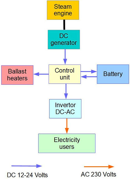
The direct current (DC) is converted to alternative current (AC 230 Volts) in the inverter. Then user gets the electricity from power sockets fitted in casing of VTES-1.
At the moment, the model VTES-1 exists as a prototype and is undergoing various tests and improvements. You can watch videos showing the tests on the following page: